| Written by Fajar | |
| Monday, 31 December 2007 | |
| User Manager Mikrotik merupakan management system yang apat dipergunakan untuk memanage user sbb:
4. Install User Manager - Buka system packages dari winbox atau terminal /system/packages/print - Jika belum ada paket user manager install dulu. Karena User-manager merupakan paket terpisah dari router os MT. Pastikan versi outer OS sama dengan versi paket user manager. Misalnya jika router os kita 2.9.50 maka paket user-manager juga harus 2.9.50. Download dari http://www.mikrotik.com/download.html, pilih salah paket user-manager-2.9.x.npk dari paket zip - Upload via Program FTP Ke Mikrotik Server - Reboot Mikrotik Server - Cek system packages spt no 1, jika user manager belum aktif diaktifkan terlebih dahulu kemudian reboot. Jika sudah aktif - buka http://192.168.0.40/userman - Jika sudah bisa terbuka halaman login user manager, berarti user manager sudah aktif.
|
Jumat, 09 Mei 2008
User Manager Untuk Hotspot Mikrotik
Selasa, 06 Mei 2008
Mikrotik crack download at local server
Download mikrotik crack bajakan
Maaf rekan2, untuk mikrotik yg download di rapidshare udah expired silahkan download yg di indowebster http://rapidshare.com/files/31374001/mikrotik-2.9.27.rar --->link ini udah expired update (2 Des 2007): http://www.indowebster.com/mikrotik2927cracked.html --->valid
Why choose Mikrotik?
Why choose Mikrotik?
- Cost effective solution
- High-speed wireless data links (Up to 108Mbps)
- Connection distance up to 70 km without repeater sites.
- IP - NAT, Routing, DHCP
- Security - Firewall, Secure Tunnels
- Control - Queues, Proxy, Accounting, HotSpot
- Fast and simple installation for base station and clients
- Reliable and instant 24 hour internet access
Basic requirements to create a wireless links are:
- Direct Line of sight between both points of presence
- Distance between points of presence is:
- up to 25 km for point-to-multipoint links
- up to 70 km for point-to-point links
- Use of 2.4 or 5.2-5.8 GHz solutions according to the local regulations. In some countries obtaining a special license might be required.
Video tutorial mikrotik
Tutorial Mikrotik VPN : EoIP
Ethernet over IP (EoIP) Tunneling is a MikroTik RouterOS protocol that creates an Ethernet tunnel between two routers on top of an IP connection. The EoIP interface appears as an Ethernet interface. When the bridging function of the router is enabled, all Ethernet level traffic (all Ethernet protocols) will be bridged just as if there where a physical Ethernet interface and cable between the two routers (with bridging enabled). This protocol makes multiple network schemes possible.
Network setups with EoIP interfaces:
- Possibility to bridge LANs over the Internet
- Possibility to bridge LANs over encrypted tunnels
- Possibility to bridge LANs over 802.11b 'ad-hoc' wireless networks
Specific Properties:
- Each EoIP tunnel interface can connect with one remote router which has a corresponding interface configured with the same 'Tunnel ID'.
- The EoIP interface appears as an Ethernet interface under the interface list.
- This interface supports all features of and Ethernet interface. IP addresses and other tunnels may be run over the interface.
- The EoIP protocol encapsulates Ethernet frames in GRE (IP protocol number 47) packets (just like PPTP) and sends them to the remote side of the EoIP tunnel.
- Maximal count of EoIP tunnels is 65536.
Tutorial Mikrotik VPN : Point to Point Tunnel Protocol (PPTP)
Summary PPTP (Point to Point Tunnel Protocol) supports encrypted tunnels over IP. The MikroTik RouterOS implementation includes support fot PPTP client and server. General applications of PPTP tunnels: * For secure router-to-router tunnels over the Internet * To link (bridge) local Intranets or LANs (when EoIP is also used) * For mobile or remote clients to remotely access an Intranet/LAN of a company (see PPTP setup for Windows for more information) Each PPTP connection is composed of a server and a client. The MikroTik RouterOS may function as a server or client – or, for various configurations, it may be the server for some connections and client for other connections. For example, the client created below could connect to a Windows 2000 server, another MikroTik Router, or another router which supports a PPTP server. Description PPTP is a secure tunnel for transporting IP traffic using PPP. PPTP encapsulates PPP in virtual lines that run over IP. PPTP incorporates PPP and MPPE (Microsoft Point to Point Encryption) to make encrypted links. The purpose of this protocol is to make well-managed secure connections between routers as well as between routers and PPTP clients (clients are available for and/or included in almost all OSs including Windows). PPTP includes PPP authentication and accounting for each PPTP connection. Full authentication and accounting of each connection may be done through a RADIUS client or locally. MPPE 40bit RC4 and MPPE 128bit RC4 encryption are supported. PPTP traffic uses TCP port 1723 and IP protocol GRE (Generic Routing Encapsulation, IP protocol ID 47), as assigned by the Internet Assigned Numbers Authority (IANA). PPTP can be used with most firewalls and routers by enabling traffic destined for TCP port 1723 and protocol 47 traffic to be routed through the firewall or router. PPTP connections may be limited or impossible to setup though a masqueraded/NAT IP connection. Please see the Microsoft and RFC links at the end of this section for more information. PPTP Client Setup Submenu level : /interface pptp-client Property Description name (name; default: pptp-out1) - interface name for reference mtu (integer; default: 1460) - Maximum Transmit Unit. The optimal value is the MTU of the interface the tunnel is working over decreased by 40 (so, for 1500-byte ethernet link, set the MTU to 1460 to avoid fragmentation of packets) mru (integer; default: 1460) - Maximum Receive Unit. The optimal value is the MTU of the interface the tunnel is working over decreased by 40 (so, for 1500-byte ethernet link, set the MRU to 1460 to avoid fragmentation of packets) connect-to (IP address)- the IP address of the PPTP server to connect to user (string)- user name to use when logging on to the remote server password (string; default: "")- user password to use when logging to the remote server profile (name; default: default) - profile to use when connecting to the remote server add-default-route (yes | no; default: no) - whether to use the server which this client is connected to as its default router (gateway) Example To set up PPTP client named test2 using username john with password john to connect to the 10.1.1.12 PPTP server and use it as the default gateway: [admin@MikroTik] interface pptp-client> add name=test2 connect-to=10.1.1.12 \ \... user=john add-default-route=yes password=john [admin@MikroTik] interface pptp-client> print Flags: X - disabled, R - running 0 X name="test2" mtu=1460 mru=1460 connect-to=10.1.1.12 user="john" password="john" profile=default add-default-route=yes [admin@MikroTik] interface pptp-client> enable 0 Monitoring PPTP Client Command name : /interface pptp-client monitor Property Description Statistics: uptime (time) - connection time displayed in days, hours, minutes, and seconds encoding (string) - encryption and encoding (if asymmetric, separated with '/') being used in this connection status (string) - status of the client: # Dialing – attempting to make a connection # Verifying password... - connection has been established to the server, password verification in progress # Connected – self-explanatory # Terminated – interface is not enabled or the other side will not establish a connection Example Example of an established connection: [admin@MikroTik] interface pptp-client> monitor test2 uptime: 4h35s encoding: MPPE 128 bit, stateless status: Connected [admin@MikroTik] interface pptp-client> PPTP Server Setup Submenu level : /interface pptp-server server [admin@MikroTik] interface pptp-server server> print enabled: no mtu: 1460 mru: 1460 authentication: mschap2 default-profile: default [admin@MikroTik] interface pptp-server server> Description The PPTP server supports unlimited connections from clients. For each current connection, a dynamic interface is created. Property Description enabled (yes | no; default: no) - defines whether PPTP server is enabled or not mtu (integer; default: 1460) - Maximum Transmit Unit. The optimal value is the MTU of the interface the tunnel is working over decreased by 40 (so, for 1500-byte ethernet link, set the MTU to 1460 to avoid fragmentation of packets) mru (integer; default: 1460) - Maximum Receive Unit. The optimal value is the MTU of the interface the tunnel is working over decreased by 40 (so, for 1500-byte ethernet link, set the MTU to 1460 to avoid fragmentation of packets) authentication (multiple choice: pap | chap | mschap1 | mschap2; default: mschap2) - authentication algorithm default-profile (name; default: default) - default profile to use Example To enable PPTP server: [admin@MikroTik] interface pptp-server server> set enabled=yes [admin@MikroTik] interface pptp-server server> print enabled: yes mtu: 1460 mru: 1460 authentication: mschap2 default-profile: default [admin@MikroTik] interface pptp-server server> PPTP Server Users Submenu level : /interface pptp-server Description There are two types of items in PPTP server configuration - static users and dynamic connections. A dynamic connection can be established if the user database or the default-profile has its local-address and remote-address set correctly. When static users are added, the default profile may be left with its default values and only P2P user (in /ppp secret) should be configured. Note that in both cases P2P users must be configured properly. Property Description name - interface name user - the name of the user that is configured statically or added dynamically Statistics: mtu - shows (cannot be set here) client's MTU client-address - shows (cannot be set here) the IP of the connected client uptime - shows how long the client is connected encoding (string) - encryption and encoding (if asymmetric, separated with '/') being used in this connection Example To add a static entry for ex1 user: [admin@MikroTik] interface pptp-server> add user=ex1 [admin@MikroTik] interface pptp-server> print Flags: X - disabled, D - dynamic, R - running # NAME USER MTU CLIENT-ADDRESS UPTIME ENC... 0 DR ex 1460 10.0.0.202 6m32s none 1 pptp-in1 ex1 [admin@MikroTik] interface pptp-server> In this example an already connected user ex is shown besides the one we just added. PPTP Router-to-Router Secure Tunnel Example The following is an example of connecting two Intranets using an encrypted PPTP tunnel over the Internet. There are two routers in this example: * [HomeOffice] Interface LocalHomeOffice 10.150.2.254/24 Interface ToInternet 192.168.80.1/24 * [RemoteOffice] Interface ToInternet 192.168.81.1/24 Interface LocalRemoteOffice 10.150.1.254/24 Each router is connected to a different ISP. One router can access another router through the Internet. On the PPTP server a user must be set up for the client: [admin@HomeOffice] ppp secret> add name=ex service=pptp password=lkjrht local-address=10.0.103.1 remote-address=10.0.103.2 [admin@HomeOffice] ppp secret> print detail Flags: X - disabled 0 name="ex" service=pptp caller-id="" password="lkjrht" profile=default local-address=10.0.103.1 remote-address=10.0.103.2 routes=="" [admin@HomeOffice] ppp secret> Then the user should be added in the PPTP server list: [admin@HomeOffice] interface pptp-server> add user=ex [admin@HomeOffice] interface pptp-server> print Flags: X - disabled, D - dynamic, R - running # NAME USER MTU CLIENT-ADDRESS UPTIME ENC... 0 pptp-in1 ex [admin@HomeOffice] interface pptp-server> And finally, the server must be enabled: [admin@HomeOffice] interface pptp-server server> set enabled=yes [admin@HomeOffice] interface pptp-server server> print enabled: yes mtu: 1460 mru: 1460 authentication: mschap2 default-profile: default [admin@HomeOffice] interface pptp-server server> Add a PPTP client to the RemoteOffice router: [admin@RemoteOffice] interface pptp-client> add connect-to=192.168.80.1 user=ex \ \... password=lkjrht disabled=no [admin@RemoteOffice] interface pptp-client> print Flags: X - disabled, R - running 0 R name="pptp-out1" mtu=1460 mru=1460 connect-to=192.168.80.1 user="ex" password="lkjrht" profile=default add-default-route=no [admin@RemoteOffice] interface pptp-client> Thus, a PPTP tunnel is created between the routers. This tunnel is like an Ethernet point-to-point connection between the routers with IP addresses 10.0.103.1 and 10.0.103.2 at each router. It enables 'direct' communication between the routers over third party networks. To route the local Intranets over the PPTP tunnel – add these routes: [admin@HomeOffice] > ip route add dst-address 10.150.1.0/24 gateway 10.0.103.2 [admin@RemoteOffice] > ip route add dst-address 10.150.2.0/24 gateway 10.0.103.1 On the PPTP server it can alternatively be done using routes parameter of the user configuration: [admin@HomeOffice] ppp secret> print detail Flags: X - disabled 0 name="ex" service=pptp caller-id="" password="lkjrht" profile=default local-address=10.0.103.1 remote-address=10.0.103.2 routes=="" [admin@HomeOffice] ppp secret> set 0 routes="10.150.1.0/24 10.0.103.2 1" [admin@HomeOffice] ppp secret> print detail Flags: X - disabled 0 name="ex" service=pptp caller-id="" password="lkjrht" profile=default local-address=10.0.103.1 remote-address=10.0.103.2 routes="10.150.1.0/24 10.0.103.2 1" [admin@HomeOffice] ppp secret> Test the PPTP tunnel connection: [admin@RemoteOffice]> /ping 10.0.103.1 10.0.103.1 pong: ttl=255 time=3 ms 10.0.103.1 pong: ttl=255 time=3 ms 10.0.103.1 pong: ttl=255 time=3 ms ping interrupted 3 packets transmitted, 3 packets received, 0% packet loss round-trip min/avg/max = 3/3.0/3 ms Test the connection through the PPTP tunnel to the LocalHomeOffice interface: [admin@RemoteOffice]> /ping 10.150.2.254 10.150.2.254 pong: ttl=255 time=3 ms 10.150.2.254 pong: ttl=255 time=3 ms 10.150.2.254 pong: ttl=255 time=3 ms ping interrupted 3 packets transmitted, 3 packets received, 0% packet loss round-trip min/avg/max = 3/3.0/3 ms To bridge a LAN over this secure tunnel, please see the example in the 'EoIP' section of the manual. To set the maximum speed for traffic over this tunnel, please consult the 'Queues' section. Connecting a Remote Client via PPTP Tunnel The following example shows how to connect a computer to a remote office network over PPTP encrypted tunnel giving that computer an IP address from the same network as the remote office has (without need of bridging over eoip tunnels) Please, consult the respective manual on how to set up a PPTP client with the software You are using. The router in this example: * [RemoteOffice] Interface ToInternet 192.168.81.1/24 Interface Office 10.150.1.254/24 The client computer can access the router through the Internet. On the PPTP server a user must be set up for the client: [admin@RemoteOffice] ppp secret> add name=ex service=pptp password=lkjrht local-address=10.150.1.254 remote-address=10.150.1.2 [admin@RemoteOffice] ppp secret> print detail Flags: X - disabled 0 name="ex" service=pptp caller-id="" password="lkjrht" profile=default local-address=10.150.1.254 remote-address=10.150.1.2 routes=="" [admin@RemoteOffice] ppp secret> Then the user should be added in the PPTP server list: [admin@RemoteOffice] interface pptp-server> add name=FromLaptop user=ex [admin@RemoteOffice] interface pptp-server> print Flags: X - disabled, D - dynamic, R - running # NAME USER MTU CLIENT-ADDRESS UPTIME ENC... 0 FromLaptop ex [admin@RemoteOffice] interface pptp-server> And the server must be enabled: [admin@RemoteOffice] interface pptp-server server> set enabled=yes [admin@RemoteOffice] interface pptp-server server> print enabled: yes mtu: 1460 mru: 1460 authentication: mschap2 default-profile: default [admin@RemoteOffice] interface pptp-server server> Finally, the proxy APR must be enabled on the 'Office' interface: [admin@RemoteOffice] interface ethernet> set Office arp=proxy-arp [admin@RemoteOffice] interface ethernet> print Flags: X - disabled, R - running # NAME MTU MAC-ADDRESS ARP 0 R ToInternet 1500 00:30:4F:0B:7B:C1 enabled 1 R Office 1500 00:30:4F:06:62:12 proxy-arp [admin@RemoteOffice] interface ethernet> ref: http://www.mikrotik.com/documentation//manual_2.7/Interface/PPTP.html
Tutorial Mikrotik dasar
Mikrotik sekarang ini banyak digunakan oleh ISP, provider hotspot, ataupun oleh pemilik warnet. Mikrotik OS menjadikan computer menjadi router network yang handal yang dilengkapi dengan berbagai fitur dan tool, baik untuk jaringan kabel maupun wireless.
Dalam tutorial kali ini penulis menyajikan pembahasan dan petunjuk sederhana dan simple dalam mengkonfigurasi mikrotik untuk keperluan-keperluan tertentu dan umum yang biasa dibutuhkan untuk server/router warnet maupun jaringan lainya, konfirugasi tersebut misalnya, untuk NAT server, Bridging, BW manajemen, dan MRTG.
Versi mikrotik yang penulis gunakan untuk tutorial ini adalah MikroTik routeros 2.9.27
silahkan download disiniTraffic Monitor with Mikrotik Tools
Dalam Memantau aliran paket data yang melewati antarmuka router Mikrotik, dapat digunakan fasilitas Torch. Keterangan lebih lanjut, dapat dibaca pada Manual Mikrotik, yaitu Torch Tools
Kita dapat memantau aliran paket berdasarkan jenis protokolnya, alamat asal, alamat tujuan serta tipe port. Dengan adanya fasilitas ini yang telah disediakan pada Packet System, ketika kita menginstalasi Mikrotik RouterOS, maka memudahkan kita dalam administrasi router, dari fasilitas ini, kita bisa menebak apakah Aliran data di mesin kita sedang Normal atau tidak. Memantau terjadinya Flooding, memantau aktifitas Malware dan sebagainya.
Menggunakannya cukup mudah, biasanya agar lebih nyaman dalam Monitoring, silahkan diaktifkan melalui Winbox, untuk masuk ke Routernya. Lebih jelasnya bisa dilihat gambar dibawah ini.
Fasilitas Torch ini bisa digunakan melalui Winbox pada menu Tools - Torch. Silahkan Klik menu Torch tersebut, nanti akan ditampilkan jendela Torchnya.

Atau Bisa juga melalui IP - ARP. Pada jendela ARP List, silahkan dipilih IP Address, MAC address yang akan di Monitor. Klik kanan untuk masuk ke menu Torch.

Perhatikan, item-item yang terdapat di jendela Torch ini, pada Manual diatas telah diberikan secara jelas keterangan terhadap item-item tersebut. Klik tombol Start untuk mengaktifkan layanan Torch ini. Sekarang kita dapat bermonitoring ria terhadap aliran paket pada mesin routernya. Jika ada trafik yang mencurigakan silahkan diambil tindakan selanjutnya.

Pada List diatas, saya memantau Aliran trafik dari IP Address (Src Address) 192.168.0.13 yang melalui Interface LAN. Jika diperhatikan, pada bagian Src port terdapat port 514 (syslog) bertipe protokol UDP (17) menuju ke IP Address (Dst Address) 192.168.0.14, dan memang saya sedang menjalankan Syslog Daemon pada PC Windows XP secara Remote untuk menyimpan log router Mikrotiknya, pada PC yang memiliki IP Address 192.168.0.13, dengan router remotenya yang memiliki IP Address 192.168.0.14, aktif di port 514 (UDP). Kita bisa memilih Alamat sumber (Src Address) pada Client yang akan kita pantau, memilih Port, Alamat tujuan, serta Protokolnya
Sumber : http://primadonal.wordpress.comBloking Mikrotik dari Scan Winbox dan Neighbour
Kadang kala para ISP atau penyedia jasa layanan tidak terlalu jeli untuk melindungi customernya. Terutama ketika melindungi router pelanggan yang menggunakan Mikrotik RouterOS(tm). Dengan menjalankan IP >> Neighbor kita bisa melihat router mikrotik lainnya yang secara fisik terhubung dengan router kita melalui jaringan di provider kita.
Untuk itu kita bisa melindunginya dengan berbagai cara misalnya memblok scan dari winbox dan neighbor kita. Berikut adalah cara yang paling mudah :
admin@mikrotik] interface bridge> filter print
Flags: X - disabled, I - invalid, D - dynamic
0 ;;; block discovery mikrotik
chain=forward in-interface=ether1 mac-protocol=ip dst-port=5678
ip-protocol=udp action=drop
1 ;;; block discovery mikrotik chain=input in-interface=ether1 mac-protocol=ip dst-port=5678 ip-protocol=udp action=drop
2 ;;; block discovery mikrotik chain=output mac-protocol=ip dst-port=5678 ip-protocol=udp action=drop
3 ;;; block discovery mikrotik chain=input in-interface=ether1 mac-protocol=ip dst-port=8291 ip-protocol=tcp action=drop
4 ;;; block winbox mikrotik chain=forward in-interface=ether1 mac-protocol=ip dst-port=8291 ip-protocol=tcp action=drop
5 ;;; block request DHCP chain=input mac-protocol=ip dst-port=68 ip-protocol=udp action=drop
6 ;;; block request DHCP chain=forward mac-protocol=ip dst-port=68 ip-protocol=udp action=drop
7 ;;; block request DHCP chain=output mac-protocol=ip dst-port=68 ip-protocol=udp action=drop
Dengan perintah tersebut kita bisa menutup beberapa scan terutama yang menggunakan winbox dan ip neighbor. Port diatas adalah bagian dari share Mikrotik RouterOS yang memang di perlukan untuk monitoring.
Sumber: http://tutorial.multisolusi.comBlocking web in mikrotik
This example will explain you “How to Block Web Sites” & “How to Stop Downloading”. I have use Web-Proxy test Package.First, Configure Proxy.
/ip proxy
enabled: yes
src-address: 0.0.0.0
port: 8080
parent-proxy: 0.0.0.0:0
cache-drive: system
cache-administrator: "ASHISH PATEL"
max-disk-cache-size: none
max-ram-cache-size: none
cache-only-on-disk: no
maximal-client-connections: 1000
maximal-server-connections: 1000
max-object-size: 512KiB
max-fresh-time: 3d
Now, Make it Transparent
/ip firewall nat
chain=dstnat protocol=tcp dst-port=80 action=redirect to-ports=8080
Make sure that your proxy is NOT a Open Proxy
/ip firewall filter chain=input in-interface=src-address=0.0.0.0/0 protocol=tcp dst-port=8080 action=drop
Now for Blocking Websites
/ip proxy access
dst-host=www.vansol27.com action=deny
It will block website http://www.vansol27.com, We can always block the same for different networks by giving src-address. It will block for particular source address.
We can also stop downloading files like.mp3, .exe, .dat, .avi,…etc.
/ip proxy access
path=*.exe action=deny
path=*.mp3 action=deny
path=*.zip action=deny
path=*.rar action=deny.
Try with this also
/ip proxy access
dst-host=:mail action=deny
This will block all the websites contain word “mail” in url.
Example: It will block www.hotmail.com, mail.yahoo.com, www.rediffmail.com
ENJOY BLOCKING…….
ref : http://satrianet.wordpress.comTipe Antena Mikrotik
Tiktube (Free Download Video Mikrotik)
The dude network monitoring dari mikrotik
 Anda kesulitan memantau jaringan LAN/ WAN, atau anda penguna Whats up?
Mikrotikers gak usah khawatir, sekarang ada "the Dude" sebuah program free dari mikrotik yg berfungsi untuk network monitoring.
The Dude network monitor is a new application by MikroTik which can dramatically improve the way you manage your network environment. It will automatically scan all devices within specified subnets, draw and layout a map of your networks, monitor services of your devices and alert you in case some service has problems.
Some of it's features:
Anda kesulitan memantau jaringan LAN/ WAN, atau anda penguna Whats up?
Mikrotikers gak usah khawatir, sekarang ada "the Dude" sebuah program free dari mikrotik yg berfungsi untuk network monitoring.
The Dude network monitor is a new application by MikroTik which can dramatically improve the way you manage your network environment. It will automatically scan all devices within specified subnets, draw and layout a map of your networks, monitor services of your devices and alert you in case some service has problems.
Some of it's features:
- The Dude is free of charge!
- Auto network discovery and layout
- Discovers any type or brand of device
- Device, Link monitoring, and notifications
- Includes SVG icons for devices, and supports custom icons and backgrounds
- Easy installation and usage
- Allows you to draw your own maps and add custom devices
- Supports SNMP, ICMP, DNS and TCP monitoring for devices that support it
- Individual Link usage monitoring and graphs
- Direct access to remote control tools for device management
- Supports remote Dude server and local client
- Runs in Linux Wine environment, MacOS Darwine, and Windows
- Best price/value ratio compared to other products (free of charge)
Spesifikasi Router Board Mikrotik untuk berbagai Kebutuhan
Mikrotik untuk Game Online
Create Dota dimesin Mikrotik
DOTA merupakan salah satu games Warcraft untuk versi online. pada gamenet games ini merupakan games terlaris selain games-games online lain seperti ragnarok, sealonline, pangya, deco dan masih banyak lagi. selain games ini gratis alias nda pake pocer, juga sangat asyik dimaenkan. disini saya coba menulis tentang bagaimana create DOTA di mesin mikrotik.
Ikuti langkah-langkah berikut :
[admin@mendem] >ip firewall nat add chain=srcnat action=masquerade out-interface=Public [admin@mendem] >ip address add address=202.xxx.xxx.xxx/32 interface=Public (xxx diisi sesuai IP public kamu) [admin@mendem] >ip firewall nat add chain=dstnat dst-address=202.xxx.xxx.xxx action=dst-nat to-addresses=192.168.***.*** (*** diisi sesuai dengan IP lokal yang ingin bisa create game) [admin@mendem] >ip firewall nat add chain=srcnat src-address=192.168.***.*** action=src-nat to-addresses=202.xxx.xxx.xxx
Agar client yg tergabung dalam LAN atau yang satu network bisa bermain bersama tambahkan perintah :
[admin@mendem] >ip firewall nat add chain=dstnat dst-address=202.xxx.xxx.1-202.xxx.xxx.254 action=netmap to-addresses=192.168.***.1-192.168.***.254 [admin@mendem] >ip firewall nat add chain=srcnat src-address=192.168.***.1-192.168.***.254 action=netmap to-addresses=202.xxx.xxx.1-202.xxx.xxx.254
Sampai disini sudah berhasil , namun ternyata ada masalah yang saya hadapi, yaitu mesin mikrotik tidak dapat saya akses atau remote dari luar jaringan dan masalah lain, port SNMP ikut-ikutan ketutup sehingga untuk menampilkan traffic cacti jadi blank …ada yang bisa membantu
Fix Dota Mik
Sebelumnya saya pernah menulis tentang Rules Create Dota di Mikrotik, namun ada kendala saat rules diaktifkan maka routerbox tidak dapat di remote, diping bahkan tidak bisa menampilkan grafik MRTG/Cacti.
Setelah beberapa kali mencoba dan mencari literatur dari mbah google akhirnya ketemu rules yang cocok untuk kepentingan remote dari luar jaringan, bisa di ping dan tentunya saya bisa melihat grafik pemakaian bandwitdh lewat MRTG/Cacti.
Rules nya seperti ini :
ip firewall nat add chain=dstnat dst-address=202. x . x . x protocol=tcp dst-port=6113 action=dst-nat to-addresses=192.168. x . x to-ports=6113
ip firewall nat add chain=dstnat dst-address=202. x . x . x protocol=udp dst-port=6113 action=dst-nat to-addresses=192.168. x . x to-ports=6113
ip firewall nat add chain=srcnat src-address=192.168. x . x protocol=tcp src-port=6113 action=src-nat to-addresses=202. x . x . x to-ports=6113
ip firewall nat add chain=srcnat src-address=192.168. x . x protocol=udp src-port=6113 action=src-nat to-addresses=202. x . x . x to-ports=6113
ip firewall nat add chain=srcnat src-address=192.168. x . x -192.168. x . x action=netmap to-address=202. x . x . x -202. x . x . x to-ports=0-65535
Mungkin sudah banyak yang tahu tentang rules diatas, harapan saya rules diatas bisa dipakai siapa saja yang memerlukannya, karena dari pengalaman yang ada sungguh sulit mencari literatur atau googling tentang rules create dota di mikrotik.
semoga membantu . taken from http://harrychanputra.wordpress.comMikrotik Issue No. 6, 29-Jan-2008
- winbox interface improvements
- new hardware announcements
- MPLS/VPLS
- RouterOS v3 is here
- New training system and new MUM!
Menemukan dengan mudah MRTG dari graphing mikrotik
Mikrotik Bandwidth Test
Overview
The Bandwidth Tester can be used to monitor the throughput only to a remote MikroTik router (either wired or wireless) and thereby help to discover network ‘bottlenecks’.
The TCP test uses the standard TCP protocol with acknowledgments and follows the TCP algorithm on how many packets to send according to latency, dropped packets, and other features in the TCP algorithm. Please review the TCP protocol for details on its internal speed settings and how to analyze its behavior. Statistics for throughput are calculated using the entire size of the TCP packet. As acknowledgments are an internal working of TCP, their size and usage of the link are not included in the throughput statistics. Therefore this statistic is not as reliable as the UDP statistic when estimating throughput.
The UDP tester sends 110% or more packets than currently reported as received on the other side of the link. To see the maximum throughput of a link, the packet size should be set for the maximum MTU allowed by the links – usually this is 1500 bytes. There is no acknowledgment required by UDP; this implementation means that the closest approximation of the throughput can be seen.
Installation
The Bandwidth Test feature is included in the 'system' package. No installation is needed for this feature
Hardware Resource Usage
!Caution! Bandwidth Test uses all available bandwidth (by default) and may impact network usability.
There is no other significant resource usage.Bandwidth Test Description
Bandwidth Test Server Configuration
[admin@MikroTik] tool> bandwidth-server
Configure network bandwidth tester service. Use authentication for disabling
unwanted bandwidth wasting. Note that remote router must be MikroTik router in
order to run the test.

session
print
 get  get value of property
 set
export
[admin@MikroTik] tool> bandwidth-server print
  enabled: yes
    authenticate: no
allocate-udp-ports-from: 2000
    max-sessions: 10
[admin@MikroTik] tool>
Setting description: enable - enable client connections for bandwidth test authenticate - communicate only with authenticated (by valid username and password) clients allocate-udp-ports-from - allocate UDP ports from max-sessions - maximal number of bandwidth-test clientsThe list of current connections can be get in session submenu:
[admin@MikroTik] tool> bandwidth-server session

print  print values of item properties
remove  remove item
[admin@MikroTik] tool> bandwidth-server session print
# FROM     PROTOCOL DIRECTION USER
0 10.0.0.202     tcp      send
[admin@MikroTik] tool>
Bandwidth Test Client Configuration
Bandwidth Test uses TCP or UDP protocol for test. The test tries to use maximum or partial amount of bandwidth to test link speed. Be aware that default test uses all available bandwidth and may impact network usability.
[admin@MikroTik] tool> bandwidth-test
Run TCP or UDP bandwidth test. Tries to use maximum or partial amount of
bandwidth to test link speed. Note that remote router must be MikroTik router
in order to run the test. Be aware that default test uses all available
bandwidth and may impact network usability.


assume-lost-time
direction  Direction of data flow
do
duration
interval
local-tx-speed
   once  print statistics once and quit
password  Password for remote user
protocol  Protocol to use for test
remote-tx-speed
   size  UDP packet size or TCP segment size
   user
[admin@MikroTik] tool> bandwidth-test
Descriptions of arguments:
address - IP address of destination host assume-lost-time - If Bandwidth Server is not responding for that time, assume that connection is lost direction - specify the direction of the test (receive, transmit, both, default is transmit) do - Script source duration - Duration of the test interval - Delay between messages (in seconds). Default is 1 second. Can be 20ms...5s local-tx-speed - Transfer test maximum speed (given in bits per second) password - Password for remote user protocol - Type of protocol to use (UDP or TCP, default TCP) remote-tx-speed - Receive test maximum speed (given in bits per second) size - Packet size in bytes (50..1500, default 512). Works only with UDP protocol user - Remote user
Bandwidth Test Example
[admin@MikroTik] tool> bandwidth-test 10.0.0.202 user=admin direction=both protocol=udp \
\... size=1500 duration=14s
status: done testing
   tx-current: 11.49Mbps
tx-10-second-average: 10.05Mbps
tx-total-average: 7.96Mbps
   rx-current: 12.55Mbps
rx-10-second-average: 10.33Mbps
rx-total-average: 8.14Mbps

[admin@MikroTik] tool>

taken from: www.mikrotik.com
Limit Different Bandwidth In Day and Night in Mikrotik
From MikroTik Wiki
There are lot many ways to limit bandwidth for day and Night, but personally I found this is the easiest way, Here it is.
I have used Simple Queue, Script and Scheduler.
Suppose we have one network 192.168.1.0/24 and want to limit Bandwidth for day and Night Time.
Network 192.168.1.0/24 Bandwidth = 06:00am – 18:00pm – 1Mbps.Bandwidth = 18:00pm – 06:00am – 2Mbps.
Create two simple queues for the same network with different Bandwidth Limit.
/queue simple #name=”Day” target-addresses=192.168.1.0/24 dst-address=0.0.0.0/0 interface=parent=none direction=both priority=8 queue=default-small/default-small limit-at=512k/512k max-limit=1M/1M total-queue=default-small #name=”Night” target-addresses=192.168.1.0/24 dst-address=0.0.0.0/0 interface= parent=none direction=both priority=8 queue=default-small/default-small limit-at=1M/1M max-limit=2M/2M total-queue=default-small
Now, write scripts
/system script
#name=”Day” source=/queue simple enable Day; /queue simple disable Night

#name=”Night” source=/queue simple enable Night; /queue simple disable Day
Finally, Schedule it
/system scheduler
#name=”Day” on-event=Day start-date=oct/13/2007 start-time=06:00:00 interval=1d

#name=”Night” on-event=Night start-date=oct/13/2007 start-time=18:00:00 interval=1d
Download manual mikrotik - ebook
Mikrotik e-books pdf
Install the Mikrotik OS using a CD
To install the RouterOS using a CD you will need a CD-writer and a blank CD. Burn the CD-image (an .iso file) to a CD. The archive with image can be downloaded here.
Follow the instructions to install RouterOS using CD-Install:
- After downloading the CD image from www.mikrotik.com you will have an ISO file on your computer:

- Open a CD Writing software, like Ahead NERO as in this example:
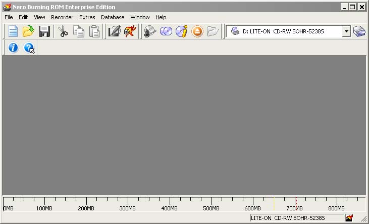
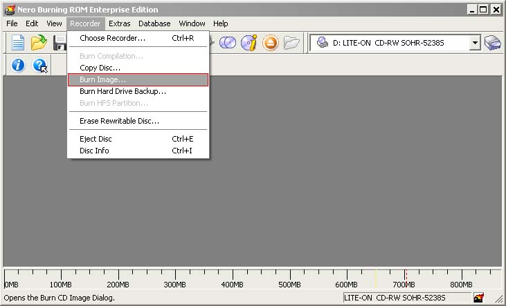
- In the program, choose Burn Image entry from the Recorder menu (there should be similary named option in all major CD burning programs):
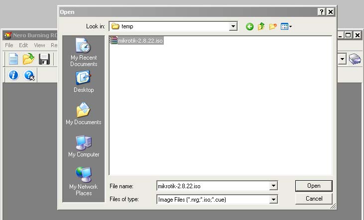
- Select the recently extracted ISO file and click Open:
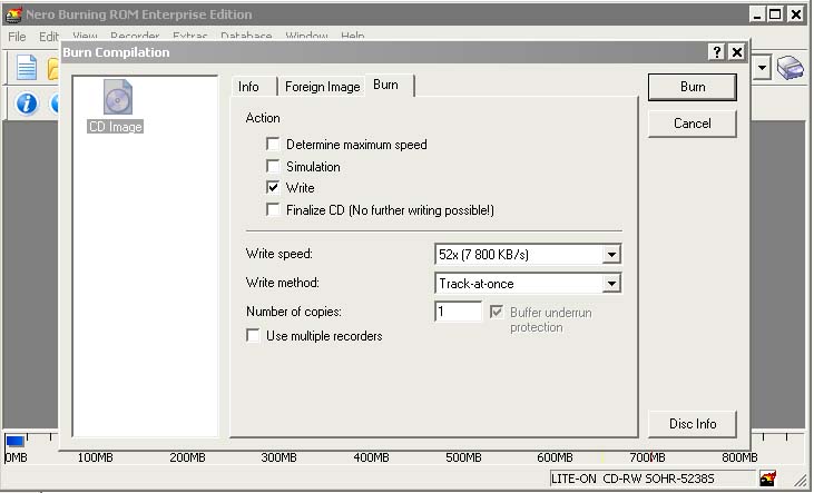
- Finally, click Burn button:
- Set the first boot device to CDROM in router's BIOS.
-
After booting from CD you will see a menu where to choose packages to install:
                Welcome to MikroTik Router Software installation

Move around menu using 'p' and 'n' or arrow keys, select with 'spacebar'.
Select all with 'a', minimum with 'm'. Press 'i' to install locally or 'r' to
install remote router or 'q' to cancel and reboot.

[X] system               [ ] isdn                  [ ] synchronous
[X] ppp                  [ ] lcd                   [ ] telephony
[X] dhcp                 [ ] ntp                   [ ] ups
[X] advanced-tools       [ ] radiolan              [ ] web-proxy
[ ] arlan                [ ] routerboard           [ ] wireless
[ ] gps                  [X] routing
[ ] hotspot              [X] security
Follow the instructions, select needed packages, and press 'i' to install the software.
-
You will be asked for 2 questions:
Warning: all data on the disk will be erased!

Continue? [y/n]
Press [Y] to continue or [N] to abort the installation.
Do you want to keep old configuration? [y/n]:
You should choose whether you want to keep old configuration (press [Y]) or to erase the configuration permanently (press [N]) and continue without saving it. For a fresh installation, press [N].
Creating partition...
Formatting disk...
The system will install selected packages. After that you will be prompted to press 'Enter'. Before doing that, remove the CD from your CD-Drive:
Software installed.
Press ENTER to reboot
Note: ref www.mikrotik.com